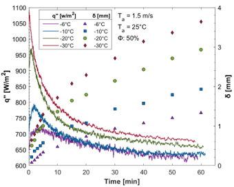
Frost formation is a major problem in a number of practical applications, such as refrigerators, Air-Conditioners, suction lines of compressors, Unmanned Aerial Vehicles (UAVs), and airplanes. Frost formation is the accumulation of frost on cooled surfaces that generates a thermal barrier between the surface and air. This leads a surface to lose its ability to heat transfer with the surrounding medium. A test systemhaving a controlled environment has been built in our laboratory. Our group has interest in understanding effect of heat flux and surface properties over dynamic frost thickness both experimentally and theoretically.

Plot showing heat flux and frost thickness versus time for multiple cold-surface temperatures ranging from −6 °C to −30 °C. The heat flux curves decrease rapidly during the first minutes and then level out, while colored markers show the corresponding frost-layer thickness growing over 60 minutes. Test conditions include air velocity of 1.5 m/s, ambient temperature of 25 °C, and relative humidity of 50%.

Our team has performed an extensive experimental study over flat and enhanced surfaces over the last decade. Our main focus has been on the frost nucleation, surface treatment, bio-inspired anti-frost surfaces, more precise modeling, real-time frost model, and experiments. The interconnections between heat flux, frost growth, and time were analyzed in the experiment.

Color-mapped simulation of frost volume fraction along a flat surface exposed to airflow from left to right. The frost layer is thickest near the leading edge and gradually decreases downstream. Colors range from red (high ice volume fraction) to blue (low volume fraction). A small box marks the experimentally observed frost layer, and a 1 mm scale bar is shown on the top right.
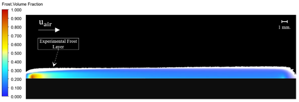
Frost formation on flat surface models via commercial CFD codes has been achieved. The frost growth was numerically modeled with Eulerian – Eulerian Multiphase modeling approach.

Photograph of an experimental frost-growth chamber illuminated with blue light. A cooled test plate is mounted inside the transparent enclosure, with a sensor probe suspended from the top. A DSLR camera with a macro lens is positioned outside the chamber for high-resolution imaging. The setup rests on an optical breadboard with vibration-damping material.

Selected research articles: