A One-Piece Lunar Regolith-Bag Garage Prototype
Excerpt from Final Report
Gweneth A. Smithers, Mary K.
NASA/Marshall Space Flight Center,
J. Scott Miller
Qualis
Corporation/Marshall Space Flight Center,
Roy M. Broughton, Jr., David Beale, and Fatma Kilinc-Balci
3.3 Full-Scale Prototype, and Erecting at MSFC
The full-scale prototype
arch was sewn at Kappler Inc. in Guntersville , AL Mt. Holly , NC
- 20 pockets at the
bottom measuring 6” x 2’ in cross-section.
- 20 pockets above the bottom pockets, measuring 6”
by 1.5’ in cross-section.
- 20 pockets that form the crest of the arch, measuring
6” by 1’ in cross-section.
Before discussing the
actual erecting at MSFC using 46 bags, prototype arch designs of a 60 bag catenary shape (e.g. Figure 3.18) were analyzed using the
funicular polygon technique. Under its own weight, the arch of Figure 3.18
revealed that it could hinge (Figure 3.19).
However, taller configurations were found to be stable (Figure 3.20),
and are expected to be able to support more weight.
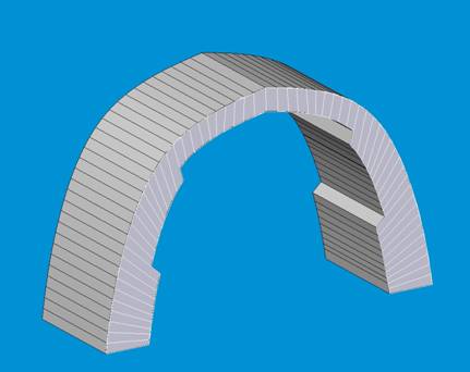
Figure 3.17. Concept Drawing of Arch
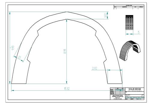
Figure 3.18. Front Dimensioned View, Dimensions in Feet.
Stability analysis using the funicular polygon (Figure
3.19) shows that the structure of Figure 3.18 can possibly form hinges. The
analysis was done assuming no applied forces were acting on the system except
vermiculite weight. One location was identified as lying between the 15th
and 16th bag starting from the left on the figure. Considering that
this structure is symmetrical, the analysis indicates that hinges will form on
the other side as well. Figure 3.19 below shows that hinges appear to form
around the 15th and the 16th bag.

Figure 3.19. Funicular Polygon Showing Possible Hinging in Arch Design
As can be seen in the image above, the hinges will
tend to open towards the outside of the bags, but since these bags are
top-connected by a stiff fabric layer, the fabric layer will prevent any
opening and therefore not allow a hinge to form. Hence this shows that this
configuration may be made stable using the top-connected bag construction. Another
analysis for a wider base below indicates that hinges can form near the 20th
and 21st bag. This formation of hinges is shown in the Figure 3.20.
These hinges will open on the inside of the bags, where there is not a
connecting fabric layer.
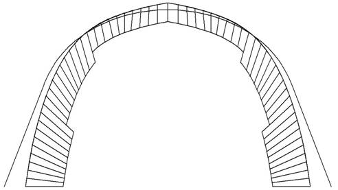
Figure 3.20. Another Set of Possible Hinge Locations
Another configuration was
analyzed to evaluate its stability. The height was increased and width
decreased. The actual dimensions are shown in Figure 3.21.
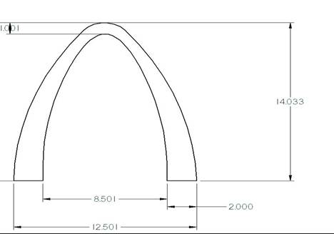
Figure
3.21. Taller design,
dimensions in feet.
On performing analysis on this structure it was seen
the funicular polygon lies inside the structure, making the structure stable.
3.22 shows the funicular polygon for this
configuration. Increasing the arch height usually improves
stability.
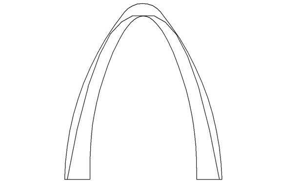
Figure 3.22. Funicular polygon of 60 bag taller, stable structure.
Erecting the MSFC Top-Connected Bag Arch
Only 46 of the 60 bags were needed when
building at MSFC. This size fitted within the construction space available,
achieved a sufficiently large structure for presentation, while shortening the
time to erect, and also demonstrating how the extra 14 bags could potentially
be used to serve as supplemental supports. Figure 3.23 shows a structure,
designed to be stable. Only 3 large bags were present as bottom bags. A wooden
frame in Figure 3.24 was constructed that served to guide erecting toward the
approximate catenary shape at 5 points, where pipes
were placed on the frame for the fabric to hang. Actual pipe locations can be
compared to design dimensions in the following the table. (Note that in the
top-connected bag arch, the pipes provide minimal support because of the
bending stiffness that this construction offers). 2x4’s attached to the bottom
and sides of the frame (not visible) served as the foundation, preventing the
bottom bags from slipping to the left or right.
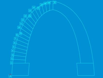
Figure 3.23. CAD Model Template to
Guide Erecting
Table 3.1 Construction
details
|
POINT |
X
|
Y
|
Actual Pipe Locations |
|
A |
0 |
0 |
|
|
1 |
1.45 |
18 |
|
|
2 |
2.151 |
23.746 |
|
|
3 |
2.985 |
29.475 |
|
|
4 |
3.9 |
35.18 |
|
|
5 |
5.1 |
40.857 |
|
|
6 |
6.4 |
46.49 |
|
|
7 |
7.9 |
52.08 |
|
|
8 |
9.6 |
57.61 |
|
|
9 |
11.59 |
63.06 |
|
|
10 |
13.806 |
68.411 |
Lower Level Pipes: x=14.5”, y=70” |
|
11 |
16.31 |
73.63 |
|
|
12 |
19.129 |
78.687 |
|
|
13 |
22.29 |
83.536 |
|
|
14 |
25.817 |
88.127 |
2nd Level Pipes: x=25.7”,
y=88” |
|
15 |
29.724 |
92.399 |
|
|
16 |
33.56 |
95.88 |
|
|
17 |
38.66 |
99.73 |
|
|
18 |
43.65 |
102.65 |
|
|
19 |
48.913 |
105.087 |
|
|
20 |
54.39 |
106.955 |
|
|
21 |
60 |
108.287 |
Top Pipe:
x=60, y=108” |
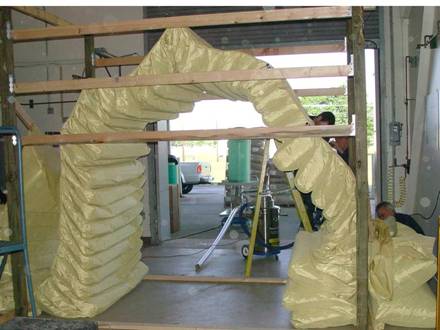
Figure 3.24. Air-Filled 46 Bag Structure, 5 pipes guiding bag filling.
After airfilling the bags,
filling of bags with vermiculite proceeded from bottom bags up. Bags were filled
using a Flexible Screw Conveyor System (Hapman,
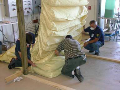
Figure 3.25: Bag Filling Process
Lower bags were filled and
formed to a near rectangular shape (Figure 3.26), while trying to provide bag
angle (notice the black zippers) as the structure grew.
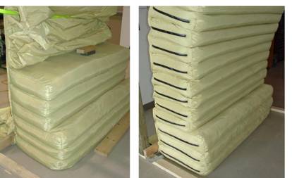
Figure
3.26. Rectangular Packed
Bags
Filling of the top 20 bags required a different
technique. Unfilled bags now hang down
from the top fabric, and cannot be filled with a rectangular shape and maintain
soil strength because of the looseness of the bag. Therefore the top 20 bags
must be filled to capacity with vermiculite, which causes them to round. With
the top three bags unfilled, the topmost filled bags were nearly touching,
which made it difficult to fill the top three bags. The maximum amount of
material that could be placed in a bag was restricted by the Helicoid Screw System, which was limited to a relatively
low compaction pressures because of the stiffness and strength limitations of
the relatively flexible and shaftless helicoid. Low compaction pressure contributed to the top
three bags not filling to the desired pressurs and
fullness. It was impossible to reach into the space and pack the bags by hand.
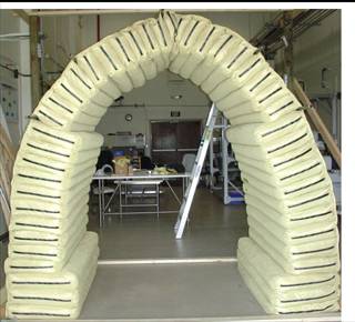
The final erected prototype is shown in Figure 3.27 (front view) and Figure
3.28(rear view). Note that in both views the pipes have been removed from their
2x4 supports, so the structure is standing without external support. We noticed
that the structure did settle ~2” once the top 3 pipe supports were removed.

Figure
3.27. Front View
Figure
3.28. Rear
View. Note the zippers.
Upon review of the standing structure and the process
of erecting, we noted the following:
- The
left side of the structure in Figure 3.27 (right side in Figure 3.28) is
the “good side”. It was built and maintained a catenary
shape very near design specifications, except for the topmost bags.
- The right side of the structure in Figure 3.27
(left side in Figure 3.28) is the “bad side”. Here we saw several flaws
that were a result of bags that were not filled to capacity.
- Figure 3.29a show that several bags on the bad
side with a flattened profile that lost the catenary-shape
curvature. Bags slipped downward despite our best attempts to erect the
structure with a catenary shape; bags slippage
was visible and occurred over a several second interval. Slippage is attributed to a shortage of
vermiculite due to incomplete packing, which did not occur on the good
side; the vermiculite grains may slide (shear) with respect to each other
inside the bags. This situation is
correctable (but difficult given that zippers are only on one end) by hand
loading more vermiculite through an open zipper and forcing material into
the bag with a plunger. A simpler fix would have been to have used an
auger-type system which deposits vermiculite under higher pressure than
the helicoid.

Figure
3.29. a. Upper left
photograph shows bags in a straight line, deviating from a caternary
shape. b. Lower left photograph show a bag that is tightly packed and bulging.
c. The upper right photograph show tightly packed 1’ bags on the good side; it
is difficult to insert a finger between the bags. d. The lower right figure shows loosely
packed bags on the bad side; the finger is easily inserted between the
bags.
4. Figure 3.29b
shows a tightly filled bag; it bulges and exhibits a hardness which can be felt
by applying finger pressure. Tightly filled bags are necessary to create bags
with sufficient vermiculite strength. Part of the internal bag pressure is a
result of loading from the bags above.
5. Figure 3.29c shows how another characteristic of a
well-built structure with tight bags. Here it is difficult to insert a finger
between the bags, implying that the bags are tightly packed with respect to
each other. Compressive and shearing loads are transmitted without failure
across the fabric boundary, from bag-to-bag.
6. Figure 3.29d shows a characteristic of inadequately
packed bags. Here it is easy to insert a finger between the bags – this may
imply the beginnings of hinge formation. The bags themselves are loosely packed
- by applying finger pressure the bags easily indented. The dark patch in the
figure represents glue that was placed in-between the bags as an experiment.
The glue did not appear to affect the structure. If the glue had affected the
structure, the glued fabric would have been in tension, and this was not the
case.
In summary, the top-connected bag structure is stable
if erected correctly - by filling the bags with sufficient pressure and
designing using masonry arch structural design principles. Several
recommendations and comments for future work are as follows:
- The
auger system used in our work was unable to fill the bags to sufficient
pressure. An auger with a central shaft would have provided higher
pressure and a more stable structure. It would have been convenient to
have had a method for easily “topping off” bags with vermiculite once the
auger was removed and filling was thought to have been complete. The top 3
bags were not filled to our satisfaction.
- We
can envision that other methods of erecting the structure are possible,
and simpler and more appropriate for erecting on the moon. Sensors could
be used to measure bag pressure and deviations of the shape from the
desired while erecting, so adjustments can be made. Shaping of bags during
and after filling was a challenging manual task.
- Analysis
can be greatly improved, by incorporating both fabric and regolith
materials and their characteristics in the analysis, perhaps using
nonlinear finite element analysis. Improved analytical methods could be
used to optimize the design. Regolith and vermiculite soil strength
parameters (determined by standard soil mechanics tests or the Lunar
Sourcebook) need to be incorporated into the modeling, along with fabric
strength parameters.